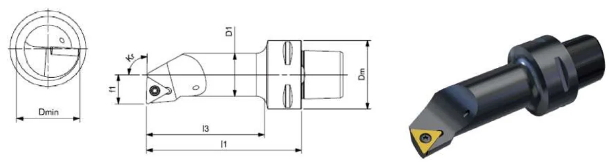
The five letters follow the ISO 5608 tool-style convention, so a STFCL body from any maker describes the same basic geometry. Reading it left to right:
| Position | Letter | Defines | On this tool |
|---|---|---|---|
| 1 | S | Insert clamping system | Screw clamp — a screw through the insert hole — the most compact arrangement, which is why it dominates small sections and boring bars |
| 2 | T | Insert shape | triangular |
| 3 | F | Tool style | 90° approach angle (κr) — offset shank, end cutting |
| 4 | C | Insert clearance angle | 7° |
| 5 | L | Cutting direction | Left hand — cuts travelling away from the chuck |
Approach angle (κr) is the angle between the main cutting edge and the feed direction, and is how these tools are normally specified. US drawings sometimes quote the side cutting edge angle instead, which is the complement (κr = 90° − SCEA) — a 95° tool is the same as a −5° SCEA tool.
STFCL seats TCMT inserts. The last block of the article number is the ISO insert size — for example PSC40-STFCL-11070-11 takes size 11. Thickness, nose radius, grade and chipbreaker are then chosen for the material and the cut, which is why Mongtec quotes the insert set with the body rather than publishing a single fixed part number.
The 7° clearance means this is a positive insert system: lower cutting forces and less deflection, which is what you want on slender bars, thin walls and smaller machines — at the cost of single-sided inserts.
Source: Mongtec PSC Product Catalog, Ver 2026.07. The five-digit block is the functional cross-section and functional length in millimetres; the final block is the ISO insert size.
| Article no. | Coupling | Capto®-size | Section × length | Insert size |
|---|---|---|---|---|
| PSC40-STFCL-11070-11 | PSC40 | C4 | 11 × 70 mm | 11 |
| PSC40-STFCL-13080-11 | PSC40 | C4 | 13 × 80 mm | 11 |
| PSC40-STFCL-17090-16 | PSC40 | C4 | 17 × 90 mm | 16 |
| PSC40-STFCL-22110-16 | PSC40 | C4 | 22 × 110 mm | 16 |
The drawing above is the published catalogue drawing. What Mongtec confirms for you is the coupling size on your turret or spindle, the reach for the operation, the insert set — and the final article number. Send the machine and the operation; the check is free.
Check STFCL for my machine →STFCL follows the ISO 5608 tool-style convention. S is the insert clamping system (screw clamp), T is the insert shape (triangular), F is the tool style giving a 90 degree approach angle, C is the insert clearance angle (7degrees), and L sets the cutting direction (left hand).
STFCL takes TCMT inserts in the size shown by the final block of the article number. The exact designation — thickness, nose radius, grade and chipbreaker — is chosen for the workpiece material and the operation, so Mongtec quotes the insert set together with the tool body.
PSC is the polygon shank coupling defined in ISO 26623 and is an open standard. PSC32, PSC40, PSC50, PSC63, PSC80 and PSC100 correspond dimensionally to coupling sizes C3, C4, C5, C6, C8 and C10, and to the German PSK designation. Mongtec is an independent tooling brand and is not affiliated with Sandvik Coromant; the sizes are quoted only to identify the coupling.
Send the machine, the coupling size on the turret or spindle, and the operation. Mongtec engineering confirms the coupling size, reach and insert selection before quoting. Dimensioned drawings are supplied by email once the enquiry is open.
Tell us the machine, the coupling size, the material and the operation. If you do not know the coupling size, send the machine model — that is enough for us to work it out. Dimensioned drawings for STFCL bodies are supplied by email once the enquiry is open.
All PSC turning tool styles · PSC / ISO 26623 overview · Driven tool holder article numbers