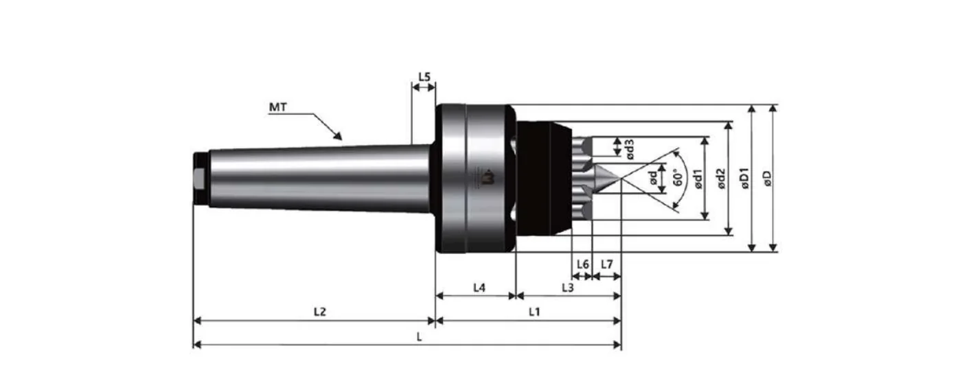
A part held in a chuck cannot be turned where the chuck is holding it, so a shaft is turned in two operations with a re-clamp in between — and the re-clamp is where concentricity between the two halves is lost. A face driver removes it. The part is held between a centre point and a set of hardened driving pins that bite into the end face; the pins carry the torque, the point carries the location, and the entire outside diameter of the shaft is exposed to the tool at once.
The catalogue's four claims, in order: minimum working-time loss and productivity improvement from one-time clamping; accuracy that auto-adjusts to the material surface; high wear performance; and wide use on NC machines. The first is the commercial argument, the second is the technical one — the pin set floats so that an as-sawn or as-forged end face still gets even engagement from every pin.
MFC is the Morse-taper execution, MT3 to MT5, in four work-size ranges: Ø18–38, Ø27–55, Ø39–75 and Ø55–100 mm, rated to 55, 60, 70 and 100 kg respectively. MFCST is the straight-shank execution of the same four sizes, with the Φd4 shank dimension in place of the taper.
Carbide hardness of the driving elements is HRA 90–91. Work direction is set by which way the MFC-type pin is fastened.
A face driver is more sensitive to the centre hole than an ordinary centre is, because the point has to locate the part while the pins are pushing it. A centre hole that is too large lets the part sit on the pins instead of the point, and one that is too small bottoms the point before the pins engage — both show up as run-out on the finished diameter. Mongtec publishes the hole size against the driver size; send the part drawing with the RFQ and the pairing is confirmed before you cut a centre hole in a hundred blanks.
Dimension symbols are the catalogue's own and refer to the dimension drawing printed for each series. Quote the series name together with the model number — the same model number is used in more than one series, so "MSNN 2601001" identifies a part and "2601001" on its own does not. A dash means the catalogue does not print a usable value for that cell; those are confirmed in writing at RFQ.
| Model No | Taper | Φd | Φd1 | Φd2 | Φd3 | ΦD | ΦD1 | L | L1 | L2 | L3 | L4 | L5 | L6 | L7 | Work Size | MAX Weight(kg) |
|---|---|---|---|---|---|---|---|---|---|---|---|---|---|---|---|---|---|
| 3107001 | MT3 | 5 | 17 | 28 | 5 | 41.4 | 41 | 141.3 | 56.3 | 85 | 31.8 | 24.5 | 6 | 5 | 5.3 | Φ18-Φ38 | 55 |
| 4107001 | MT4 | 5 | 17 | 28 | 5 | 41.4 | 41 | 164.3 | 56.3 | 108 | 31.8 | 24.5 | 8 | 5 | 5.3 | Φ18-Φ38 | 55 |
| 5107001 | MT5 | 5 | 17 | 28 | 5 | 41.4 | 41 | 192.3 | 56.3 | 136 | 31.8 | 24.5 | 8 | 5 | 5.3 | Φ18-Φ38 | 55 |
| 3207001 | MT3 | 9 | 26 | 38 | 7 | 52 | 51.4 | 148.8 | 63.8 | 85 | 36.8 | 27 | 6 | 6.5 | 8.8 | Φ27-Φ55 | 60 |
| 4207001 | MT4 | 9 | 26 | 38 | 7 | 52 | 51.4 | 171.8 | 63.8 | 108 | 36.8 | 27 | 8 | 6.5 | 8.8 | Φ27-Φ55 | 60 |
| 5207001 | MT5 | 9 | 26 | 38 | 7 | 52 | 51.4 | 199.8 | 63.8 | 136 | 36.8 | 27 | 8 | 6.5 | 8.8 | Φ27-Φ55 | 60 |
| 3307001 | MT3 | 14 | 38 | 52 | 9 | 68 | 67.4 | 168 | 83 | 85 | 47 | 36 | 6 | 9 | 13 | Φ39-Φ75 | 70 |
| 4307001 | MT4 | 14 | 38 | 52 | 9 | 68 | 67.4 | 191 | 83 | 108 | 47 | 36 | 8 | 9 | 13 | Φ39-Φ75 | 70 |
| 5307001 | MT5 | 14 | 38 | 52 | 9 | 68 | 67.4 | 219 | 83 | 136 | 47 | 36 | 8 | 9 | 13 | Φ39-Φ75 | 70 |
| 4407001 | MT4 | 18 | 54 | 72 | 14 | 83.5 | 82.5 | 200.6 | 92.6 | 108 | 57.6 | 35 | 8 | 11 | 15.6 | Φ55-Φ100 | 100 |
| 5407001 | MT5 | 18 | 54 | 72 | 14 | 83.5 | 82.5 | 228.6 | 92.6 | 136 | 57.6 | 35 | 8 | 11 | 15.6 | Φ55-Φ100 | 100 |
| Model No | Φd | Φd1 | Φd2 | Φd3 | Φd4 | ΦD | ΦD1 | L | L1 | L2 | L3 | L4 | L6 | L7 | Work Size | MAX Weight(kg) |
|---|---|---|---|---|---|---|---|---|---|---|---|---|---|---|---|---|
| TS0107001 | 5 | 17 | 28 | 5 | 35 | 41.4 | 41 | 141.3 | 56.3 | 85 | 31.8 | 24.5 | 5 | 5.3 | Φ18-Φ38 | 55 |
| TS0207001 | 9 | 26 | 28 | 7 | 35 | 52 | 51.4 | 148.3 | 63.8 | 85 | 36.8 | 27 | 6.5 | 8.8 | Φ27-Φ55 | 60 |
| TS0307001 | 14 | 38 | 52 | 9 | 35 | 68 | 67.4 | 168 | 83 | 85 | 47 | 36 | 9 | 13 | Φ39-Φ75 | 70 |
| TS0407001 | 18 | 54 | 72 | 14 | 41 | 83.5 | 82.5 | 177.6 | 92.6 | 85 | 57.6 | 35 | 11 | 15.6 | Φ55-Φ100 | 100 |
Source: Mongtec Precision Center catalogue, Ver 2026 (drive centres).
For shaft work between centres, yes — that is the point of it. The part is driven from the end face, so the whole outside diameter can be turned in one clamping. It does not replace a chuck for flanged, short or unbalanced parts.
Matched to the driver size. Mongtec publishes a face-driver centre-hole size table and the limits either side of it; too large and the part rides on the pins, too small and the point bottoms out. Confirm against your part drawing at RFQ.
By the fastening direction of the MFC-type pin, per the catalogue. The same driver can be set for either work direction.
MFC mounts on a Morse taper (MT3, MT4, MT5). MFCST is the straight-shank version of the same four work-size ranges — choose by what your tailstock or spindle accepts.