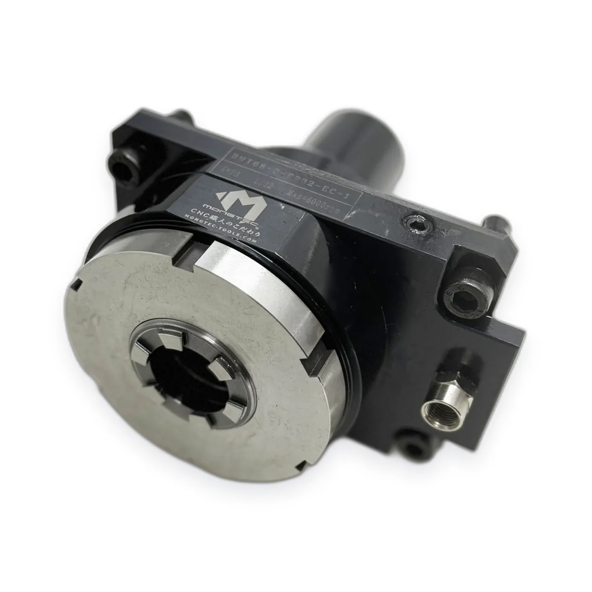
Axial or radial? Choosing the driven tool holder orientation
Every driven tool holder answers one question: which direction does the cutter point? The choice is set by the feature on the drawing, then adjusted by what the turret and the neighbouring stations allow.
Axial (0°) — face work
Holes and threads parallel to the spindle centreline, end milling on the part face, engraving on the face. On Y-axis machines, off-centre face features too. Browse axial (0°) driven tool holders.
Radial (90°) — cross work
Cross holes, cross tapping, flats, keyways, circumferential slots. Radial holders carry the cutter closer to the turret face, which matters for interference on short parts and large chucks. Browse radial (90°) driven tool holders.
When neither plain type fits
Offset axial shifts the output from the station centre to clear a chuck or tailstock. Retracted radial pulls the cutter back toward the turret for tight interference situations. Double-output types put two cutters in one station — worth considering when stations are the bottleneck. Universal (adjustable) holders cover the feature that is neither 0° nor 90°.
What decides it in practice
The feature direction on the part drawing — non-negotiable.
Interference: chuck diameter, part length, tailstock, neighbouring stations.
The turret interface and its coupling — which holders exist for your machine at all; check your machine model page.
Duty: speed and torque for the operation, and coolant routing.